Unlocking the Secrets of Transformer Schematics
Ever wondered how electricity magically transforms from high voltage power lines to the safe, usable power in your home? The secret lies within the ingenious design of the transformer, and understanding its blueprint – the transformer schematic – is key to unlocking its mysteries. This article delves into the world of transformer schematics, exploring their significance, interpretations, and real-world implications.
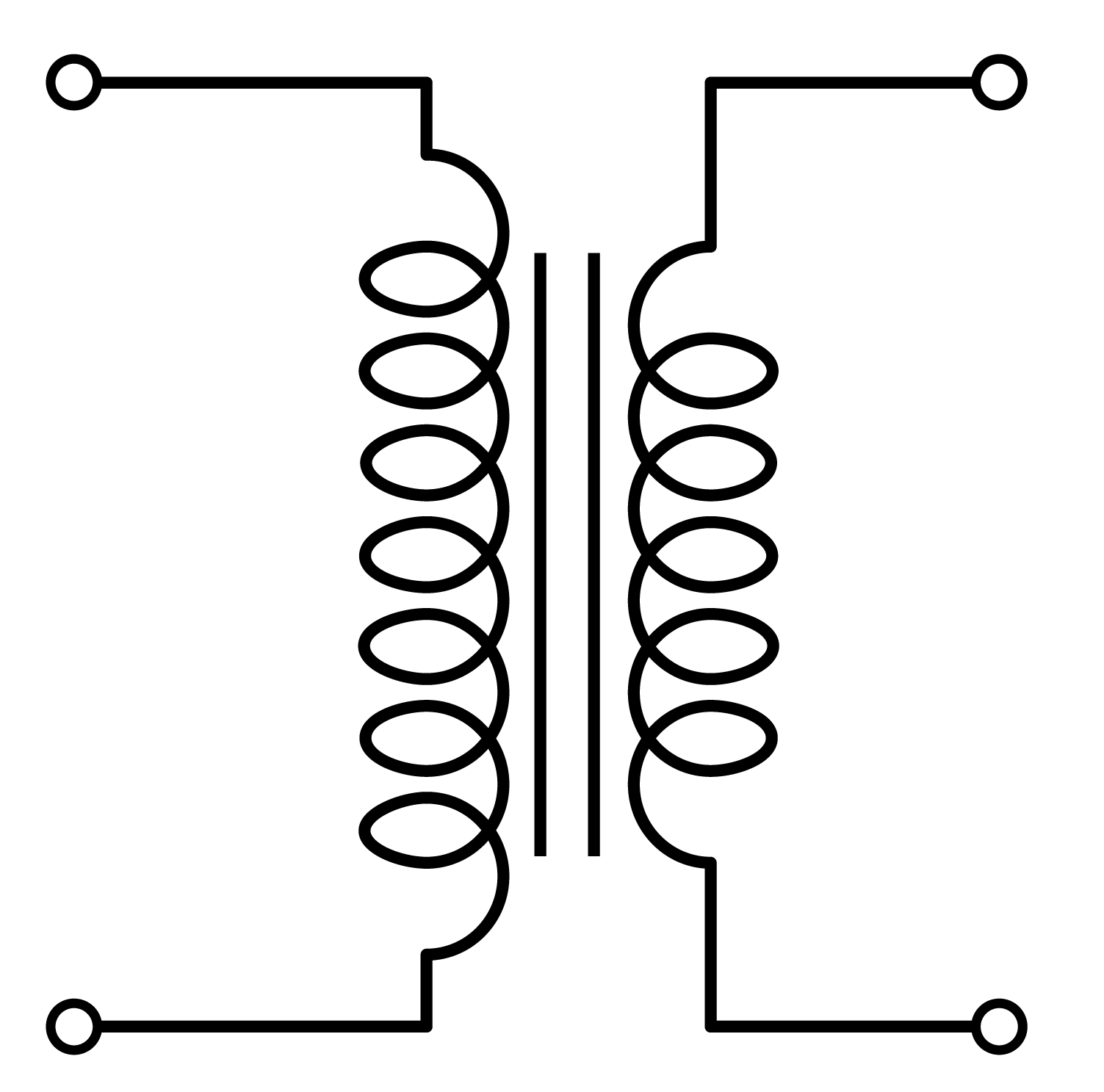
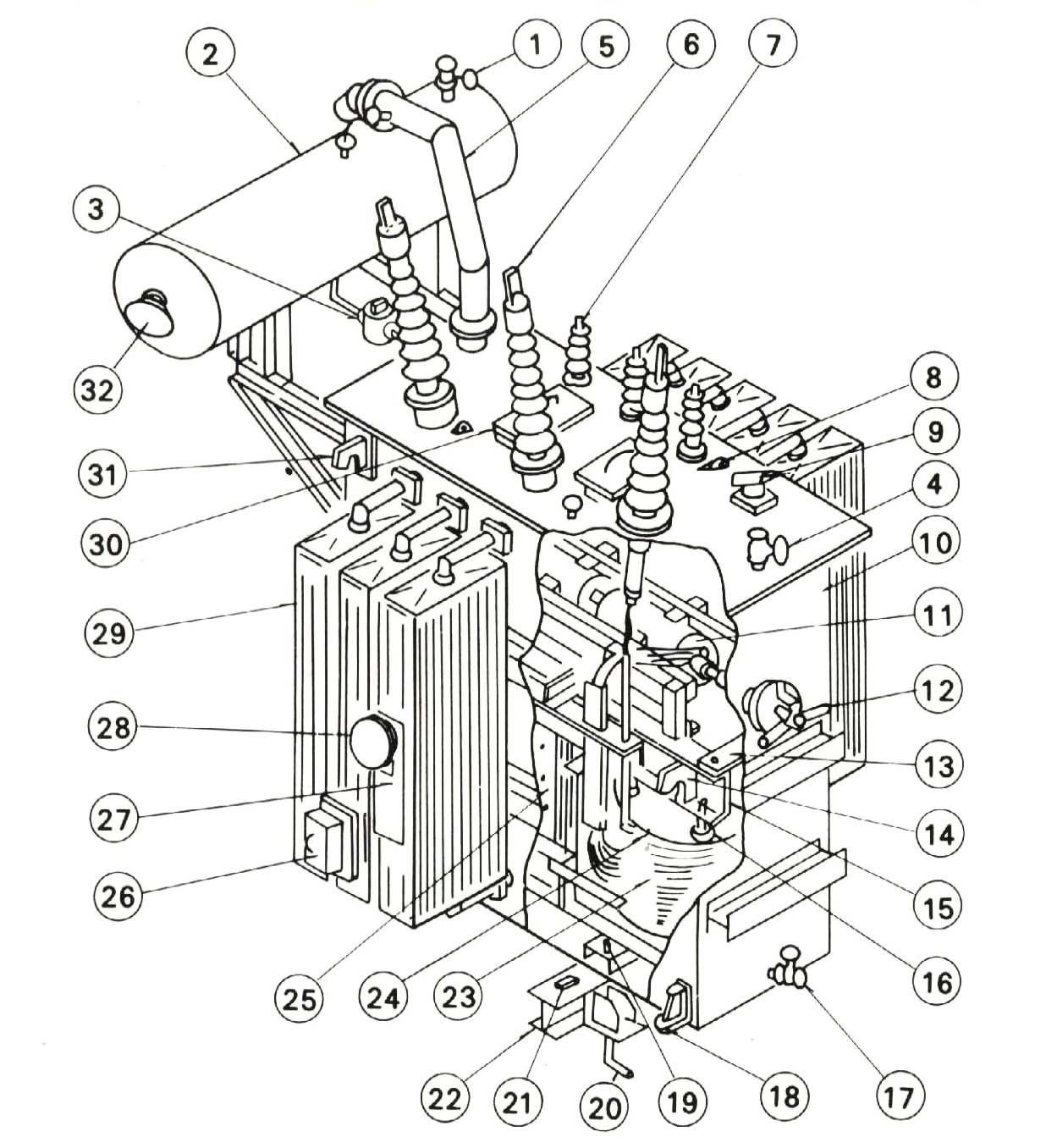
A transformer schematic is a visual representation of a transformer's internal workings, depicting the arrangement of its core, windings, and connections. It acts as a roadmap for anyone working with transformers, be it an engineer designing a power grid or a technician troubleshooting a faulty appliance. By deciphering these diagrams, we can understand the flow of energy, predict transformer behavior, and ensure efficient and safe operation.
The concept of electromagnetic induction, the foundation upon which transformers operate, was discovered by Michael Faraday in the 19th century. This discovery paved the way for the development of the first transformers, revolutionizing power distribution. Early transformer diagrams were simple, but as transformer technology advanced, so did the complexity of their schematics. Today, transformer schematic diagrams encompass a wide range of designs, reflecting the diversity of transformer applications.
The importance of a transformer wiring diagram cannot be overstated. It provides a standardized language for engineers and technicians, facilitating communication and collaboration. These diagrams play a vital role in troubleshooting, maintenance, and repair, allowing professionals to pinpoint issues quickly and accurately. Moreover, transformer schematics are essential for designing new transformer systems, optimizing performance, and ensuring safety.
Without a proper understanding of transformer electrical diagrams, the risks of misconnections, improper operation, and potential hazards increase significantly. A well-interpreted schematic allows for accurate component identification, connection verification, and the prevention of costly errors. It's the key to harnessing the power of transformers effectively and safely.
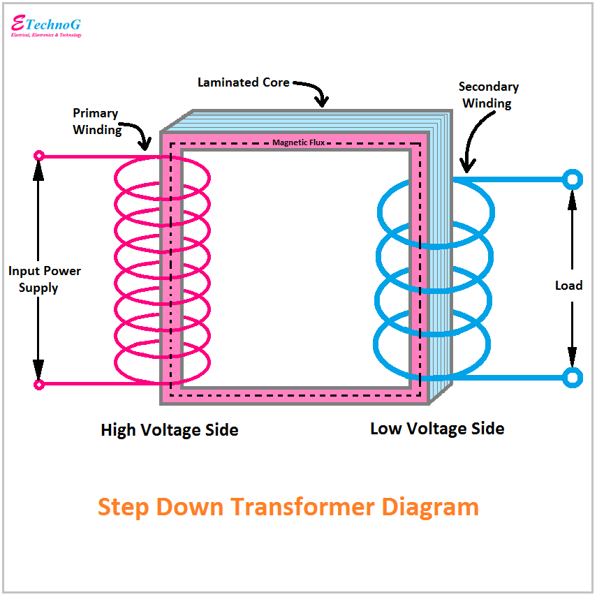
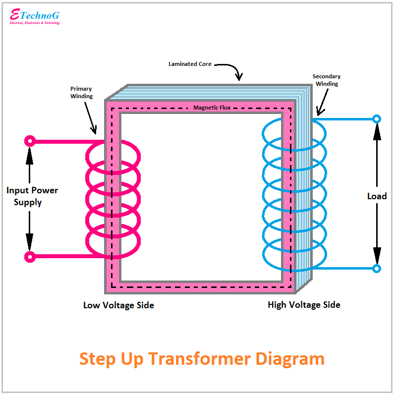
A basic transformer diagram depicts two sets of windings – the primary and secondary – wound around a ferromagnetic core. The primary winding receives the input voltage, while the secondary winding delivers the output voltage. The ratio of turns in the primary and secondary windings determines the voltage transformation ratio.
Benefits of understanding transformer diagrams include accurate troubleshooting, enabling quick identification of faulty components; efficient design and implementation of new transformer systems; and enhanced safety by preventing misconnections and ensuring proper operation.
Creating a transformer from a schematic involves winding the coils according to the specified number of turns, assembling the core, and connecting the windings appropriately. Successful examples include transformers in power distribution networks, electronic devices, and industrial machinery.
Advantages and Disadvantages of Understanding Transformer Schematics
| Advantages | Disadvantages |
|---|---|
| Efficient Troubleshooting | Requires Technical Knowledge |
| Safe Operation | Can be Complex for Intricate Designs |
| Optimized Design |
Best practices for interpreting transformer schematics include understanding standard symbols, tracing the current flow, verifying connections, and considering the transformer's specifications.
Real examples of transformer applications include power distribution transformers, isolation transformers, instrument transformers, and autotransformers.
Challenges in working with transformer schematics include complex diagrams for specialized transformers, variations in symbol usage, and understanding the underlying principles of transformer operation. Solutions involve utilizing software tools, consulting relevant standards, and seeking expert advice when needed.
Frequently Asked Questions:
1. What is a transformer schematic? (A visual representation of a transformer's internal wiring and connections)
2. Why are transformer schematics important? (For troubleshooting, design, and safe operation)
3. What are the basic components of a transformer schematic? (Primary winding, secondary winding, and core)
4. How do you read a transformer schematic? (By understanding the symbols and tracing the current flow)
5. What are some common symbols used in transformer schematics? (Symbols for windings, core, connections, etc.)
6. How can transformer schematics help with troubleshooting? (By pinpointing faulty components and connections)
7. What are the different types of transformer schematics? (Single-phase, three-phase, autotransformer, etc.)
8. Where can I find resources on transformer schematics? (Textbooks, online tutorials, manufacturer datasheets)
Tips and tricks for working with transformer diagrams include using software tools for simulation and analysis, cross-referencing with manufacturer datasheets, and practicing with simple diagrams before tackling complex ones.
In conclusion, understanding transformer schematics is paramount for anyone working with these essential devices. From ensuring safe operation and efficient troubleshooting to designing innovative transformer systems, the ability to interpret these diagrams is crucial. By mastering the language of transformer schematics, we can unlock the full potential of these powerful tools and pave the way for a more electrified future. Investing time in learning about transformer diagrams empowers us to work with them confidently and effectively. Take advantage of available resources, practice reading and interpreting different types of schematics, and delve deeper into the fascinating world of transformer technology. This knowledge will undoubtedly prove valuable in numerous applications, from simple household repairs to complex industrial projects.
Rav4 prime the ultimate electrified suv
Dive into the world of my hero academia a beginners guide
Navigating wells fargo minimum daily balance requirements


