Decoding Timer Relay Contact Symbols: Your Ultimate Guide
Ever wondered about those cryptic markings on a timer relay diagram? They're not just random squiggles; they're a language, and understanding it is key to harnessing the power of time-based control in your electrical circuits. This guide unlocks the secrets of timer relay contact symbols, empowering you to design and troubleshoot circuits with confidence.
Timer relays, those ingenious devices that introduce the element of time into electrical systems, are ubiquitous in modern technology. From simple appliances to complex industrial machinery, these components automate processes, enhance safety, and optimize energy consumption. At the heart of their operation lies a precise arrangement of contacts, each with a specific symbol that dictates its function. Deciphering these symbols is paramount to effectively utilizing these versatile devices.
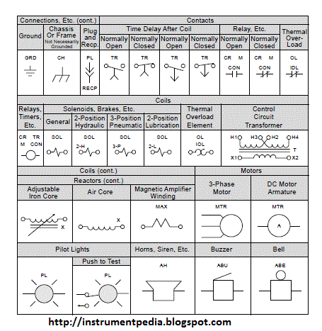
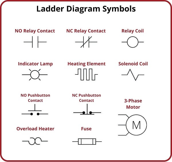
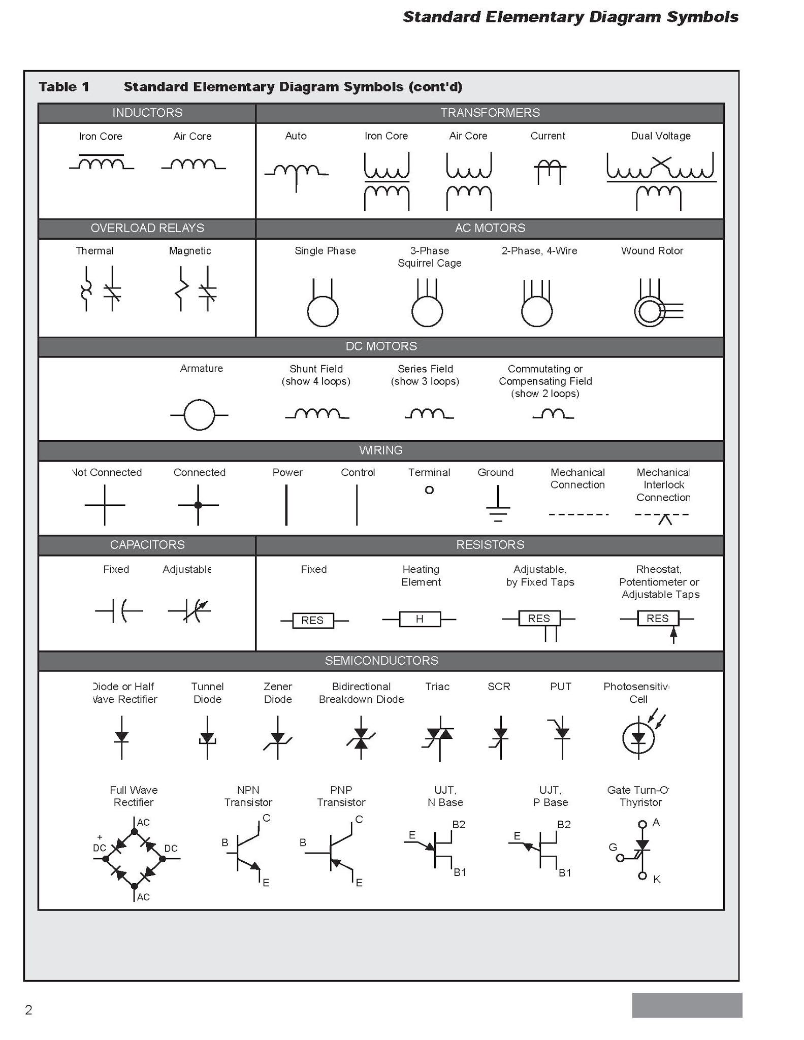
The graphical representations, known as timer relay contact symbols, provide a visual shorthand for the complex actions happening within the relay. They indicate whether a contact is normally open (NO), normally closed (NC), or timed, and how it behaves when the relay is energized or de-energized. Mastering these symbols is like learning the alphabet of time-based control, allowing you to read and interpret circuit diagrams with ease.
Historically, relay contact symbology evolved alongside the development of relay technology itself. Early representations were often crude and varied, leading to confusion and misinterpretations. Standardization efforts, driven by the need for clear communication in increasingly complex electrical systems, eventually resulted in the widely adopted symbols used today. These standardized notations ensure consistent understanding across different industries and applications.
The importance of standardized timer relay contact symbols cannot be overstated. They are fundamental for accurate circuit design, efficient troubleshooting, and effective communication between engineers and technicians. Misinterpreting a single symbol can lead to faulty operation, safety hazards, and costly downtime. Therefore, a solid grasp of these symbols is essential for anyone working with timer relays.
A normally open (NO) contact, represented by two parallel lines, is open in its default, unenergized state. When the relay coil is energized, the contact closes, allowing current to flow. Conversely, a normally closed (NC) contact, depicted by two parallel lines with a diagonal slash, is closed in its default state and opens when the relay is energized. Timed contacts, often represented with specific time-related markings, introduce delays and timed actions to the circuit's operation.
One benefit of using timer relays is their ability to automate processes. For example, a timer relay can be used to automatically turn on lights at dusk and off at dawn. Another benefit is their ability to improve safety. For example, a timer relay can be used to automatically shut off a machine if it overloads. Finally, timer relays can help to optimize energy consumption. For example, a timer relay can be used to automatically turn off lights in a room when it is not occupied.
A simple action plan for implementing a timer relay involves identifying the desired timing function, selecting the appropriate timer relay type, connecting the relay according to the circuit diagram, and testing the functionality. A successful example is using a timer relay to control a ventilation system, activating it only during specific hours.
Advantages and Disadvantages of Using Timer Relays
| Advantages | Disadvantages |
|---|---|
| Automation of Processes | Limited Complexity for Highly Sophisticated Tasks |
| Enhanced Safety Features | Potential for Mechanical Failure in Older Models |
| Optimized Energy Consumption | Can Be Bulky Compared to Solid-State Alternatives |
Frequently Asked Questions:
1. What is a timer relay? - A timer relay is an electrical switch that operates based on a pre-set time delay.
2. What are the common types of timer relays? - Common types include on-delay, off-delay, and interval timers.
3. How do I choose the right timer relay? - Selection depends on the specific timing requirements of your application.
4. What are the key considerations for wiring a timer relay? - Ensure correct voltage and current ratings, and follow the circuit diagram precisely.
5. What are the common troubleshooting steps for timer relays? - Check the power supply, wiring connections, and the timer relay itself.
6. What safety precautions should I take when working with timer relays? - Always disconnect power before working on any electrical circuit.
7. What are the typical applications of timer relays? - Timer relays are used in lighting control, HVAC systems, industrial automation, and many other applications.
8. Where can I find more information on timer relay contact symbols? - Consult relay datasheets, electrical engineering textbooks, and online resources.
In conclusion, understanding timer relay contact symbols is crucial for effectively designing, implementing, and troubleshooting time-based control circuits. These symbols are more than just lines and squiggles; they represent a precise language that governs the operation of essential components in countless applications. By mastering this language, you unlock the ability to harness the power of time in your electrical systems, enabling automation, enhancing safety, and optimizing performance. From simple household appliances to complex industrial machinery, timer relays and their associated contact symbols play a vital role in shaping our technological landscape. So, take the time to learn these symbols; the knowledge will undoubtedly empower you in your electrical endeavors and contribute to a deeper understanding of the world around us.
Comenity pay bh web
Cincinnatis climate control champions navigating your hvac needs
Decoding the enigma of black brown and blue wires


