Decoding the Mystical Language of Relay Symbols
Ever feel like you're deciphering ancient hieroglyphs when staring at an electrical diagram? Those cryptic symbols, like the ones representing relays, hold the key to understanding the complex dance of electrons within a circuit. But fear not, aspiring circuit whisperer, for we're about to embark on a journey to demystify the language of relay symbols, empowering you to navigate the electrical landscape with confidence and grace.
Relay symbols, those elegantly simple yet powerful representations, are the shorthand of electrical engineers. They encapsulate the essence of a relay's function – acting as an electrically controlled switch. Imagine them as the gatekeepers of electrical flow, directing currents with a flick of an electromagnetic wrist. Mastering these symbols is akin to learning the secret handshake of the electrical world, allowing you to communicate effectively with other engineers and unlock the secrets held within circuit diagrams.
The evolution of the relay symbol mirrors the development of the relay itself, from its humble beginnings in telegraphy to its ubiquitous presence in modern electronics. Early representations were often detailed illustrations of the relay's internal workings, gradually evolving into the streamlined, standardized symbols we use today. These symbols, governed by organizations like the IEC and ANSI, ensure a common language across the globe, facilitating collaboration and preventing misinterpretations that could lead to circuit malfunctions.
Understanding the nuances of a relay schematic is crucial for anyone working with electrical circuits. Misinterpreting a relay's configuration can lead to anything from a minor inconvenience to a catastrophic system failure. Imagine a relay intended to activate a safety mechanism failing to trigger due to a misread symbol – the consequences could be dire. Thus, a firm grasp of relay symbology is not merely a matter of technical proficiency, but a matter of safety and responsibility.
The significance of relay symbols extends beyond mere representation; they are essential tools for circuit design, analysis, and troubleshooting. These visual cues allow engineers to quickly identify relay types, coil voltages, contact configurations, and other critical parameters. They are the building blocks of complex circuit diagrams, enabling engineers to visualize the intricate interplay of components and predict circuit behavior with precision.
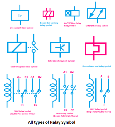
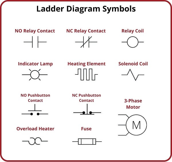
A relay symbol typically consists of a coil and contacts. The coil, represented by a rectangle or circle, signifies the electromagnet that controls the relay's switching action. The contacts, depicted as lines and arcs, represent the electrical connections that are made or broken when the relay is energized. Variations in the symbol indicate different contact configurations, such as normally open (NO) or normally closed (NC), providing crucial information about the relay's behavior.
Benefits of understanding relay symbols include: streamlined circuit analysis, efficient communication among engineers, and accurate circuit implementation. For example, knowing the symbol for a latching relay allows an engineer to quickly identify a circuit that maintains its state even after the control signal is removed. Similarly, recognizing the symbol for a time-delay relay enables anticipation of a delayed switching action within the circuit.
Advantages and Disadvantages of Standardized Relay Symbols
| Advantages | Disadvantages |
|---|---|
| Universal understanding | Can be complex for beginners |
| Simplified circuit analysis | Requires learning and memorization |
| Efficient communication | Minor variations exist between standards |
Best Practices for Implementing Relay Symbols: 1. Adhere to recognized standards (IEC, ANSI). 2. Clearly label all relay symbols with descriptive designations. 3. Ensure consistent use of symbols throughout the circuit diagram. 4. Provide a legend explaining any non-standard symbols used. 5. Use software tools that offer standardized symbol libraries.
Frequently Asked Questions: 1. What is the difference between NO and NC contacts? 2. How do I identify a latching relay symbol? 3. What are the common standards for relay symbols? 4. How do I represent a time-delay relay in a circuit diagram? 5. Where can I find resources to learn more about relay symbols? 6. What software can I use to draw circuit diagrams with relay symbols? 7. How do I interpret complex relay symbols? 8. What are the common mistakes to avoid when using relay symbols?
In conclusion, mastering the language of relay symbols is an essential skill for anyone working with electrical circuits. These symbols are more than just simple diagrams; they are the keys to understanding the intricate workings of electrical systems. From simplifying circuit analysis to ensuring accurate implementation, the benefits of understanding relay symbology are undeniable. By embracing these symbols, we empower ourselves to communicate effectively within the electrical world, unlocking the potential for innovation and creating circuits that power our modern lives. As you delve deeper into the world of circuit design, remember that these symbols are your allies, guiding you through the complex landscape of electrical engineering. So, embrace the challenge, decipher the symbols, and unlock the power within.
Unlocking the ballon dor ceremony date mystery
Elevating the essence chemistry project covers portadas para proyecto de quimica
The future of football dissecting this years top quarterback prospects


