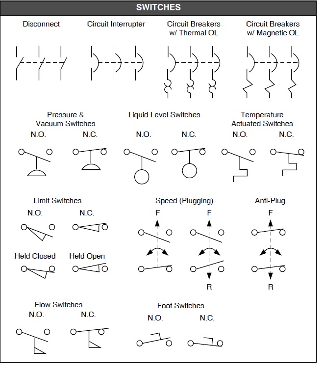
Decoding the Matrix: Electrical Symbols for Switches and Outlets
Ever stared at a wiring diagram and felt like you were deciphering an alien language? Those cryptic lines, circles, and squiggles aren't random doodles; they're a crucial communication tool: electrical symbols for switches and outlets. Understanding these symbols is paramount for anyone working with electrical systems, from seasoned electricians to DIY enthusiasts.
Electrical diagrams serve as the blueprints of electrical installations. They map out the flow of electricity, the placement of devices, and the intricate connections that power our homes and businesses. Without a standardized system of symbols, these diagrams would be chaotic and incomprehensible, leading to potentially dangerous errors during installation and maintenance.
Imagine trying to assemble a complex piece of furniture without instructions. You might eventually figure it out, but the process would be fraught with frustration and potential mistakes. Electrical symbols for switches and outlets play a similar role as those assembly instructions. They provide a clear and concise language for understanding how electrical systems are designed and function.
The evolution of these symbols is intertwined with the development of electricity itself. As electrical systems became more complex, so did the need for a standardized way to represent them. Early diagrams were often crude and varied, but over time, a more universal system emerged, driven by the need for clarity and safety. Organizations like the IEEE (Institute of Electrical and Electronics Engineers) and IEC (International Electrotechnical Commission) have played a significant role in standardizing these symbols internationally.
Misinterpreting a switch symbol on a diagram could mean the difference between a properly functioning light fixture and a short circuit. This underscores the critical importance of correctly understanding these representations. The standardization of switch and outlet graphical representations allows electricians worldwide to work together, share designs, and troubleshoot problems effectively.
A simple toggle switch, for instance, is represented by a small line with a perpendicular line branching off. Variations on this basic symbol indicate different types of switches, such as three-way or four-way switches. Outlet symbols visually represent the physical configuration of the outlet, showing the number of receptacles and whether they are grounded.
Understanding outlet symbols is crucial for ensuring compatibility and safety. Different types of outlets are designed for specific voltage and current requirements. Using the wrong outlet could damage equipment or even create a fire hazard. These symbols help electricians select the appropriate outlets for various applications.
Benefits of Standardized Electrical Symbols:
1. Clarity and Communication: Symbols provide a universal language, ensuring accurate communication between electricians, engineers, and DIYers.
2. Safety: Proper interpretation of symbols prevents errors during installation and maintenance, reducing the risk of electrical hazards.
3. Efficiency: Symbols simplify complex wiring diagrams, making them easier to read and understand, which saves time and improves workflow.
Best Practices:
1. Consult Standardized References: Always refer to official documentation from IEEE or IEC for accurate symbol interpretations.
2. Double-Check: Before starting any electrical work, verify the symbols on the diagram and ensure you understand their meaning.
3. Use Clear Diagrams: When creating diagrams, use clear and concise symbols to avoid ambiguity.
FAQs:
1. Where can I find a comprehensive list of electrical symbols? (Answer: IEEE and IEC publications)
2. Are there different symbols for international standards? (Answer: Yes, minor variations can exist)
3. What does a circle with a dot inside represent? (Answer: A ceiling-mounted light fixture)
4. How do I distinguish between a switch and an outlet symbol? (Answer: Outlet symbols often resemble the physical outlet configuration)
5. Why are some switch symbols more complex than others? (Answer: They represent different switch functions, like three-way or dimmer switches)
6. What are the common symbols for receptacles? (Answer: Variations of a circle with lines or arcs indicating the number of slots and grounding)
7. How can I learn to interpret electrical diagrams? (Answer: Studying resources from IEEE/IEC and practicing reading diagrams)
8. Are there online resources for learning about electrical symbols? (Answer: Yes, numerous websites and apps provide information and tutorials)
Advantages and Disadvantages of Standardized Electrical Symbols
While standardized symbols offer numerous benefits, some minor drawbacks exist:
| Advantages | Disadvantages |
|---|---|
| Improved communication | Requires learning and memorization |
| Enhanced safety | Minor variations between standards can sometimes cause confusion |
| Increased efficiency |
In conclusion, electrical symbols for switches and outlets are not just abstract markings on a diagram; they are the essential building blocks of safe and efficient electrical systems. They provide a universal language that enables clear communication, prevents errors, and ensures the smooth functioning of our electrical infrastructure. From the simple flip of a light switch to the complex wiring of a power grid, these symbols play a crucial role. Mastering their meaning empowers us to confidently navigate the electrical landscape and harness the power that illuminates and connects our world. Understanding these symbols is a fundamental skill for anyone working with electricity, contributing to both safety and effective communication. Take the time to study and familiarize yourself with these symbols – it's an investment that will pay dividends in your electrical endeavors.
The como se llaman los de bts phenomenon why were all obsessed
Winterizing your sanctuary investing in cozy coziness
Unraveling the mystery of afton family animatronic identities


