Decoding the Elegance of Pneumatic Schematics
There's a certain understated elegance in the precision of a well-drawn pneumatic schematic. Like a perfectly tailored suit, each line, each symbol, contributes to a cohesive whole, communicating a complex system with a quiet authority.
Understanding pneumatic symbols is akin to possessing a secret language. It allows one to decipher the intricate workings of compressed air systems, from the simplest air compressor to the most complex automated machinery. These visual representations are the backbone of pneumatic system design, troubleshooting, and maintenance.
Imagine trying to navigate a bustling city without street signs. Similarly, navigating the complexities of a pneumatic system without a grasp of standard pneumatic symbols is a daunting, if not impossible, task. A readily available resource, often in the form of a basic pneumatic symbols PDF, is crucial for anyone working with these systems.
The visual language of pneumatic schematics has evolved over time, driven by the need for standardization and clarity. The International Organization for Standardization (ISO) plays a significant role in maintaining this uniformity, ensuring that a directional control valve symbol signifies the same function regardless of the manufacturer or country.
One of the key issues surrounding pneumatic symbols is accessibility to clear and concise reference materials. While numerous pneumatic symbols PDF documents exist, ensuring they are up-to-date with the latest ISO standards is essential for accurate interpretation and application.
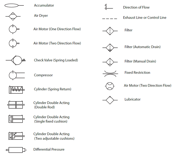
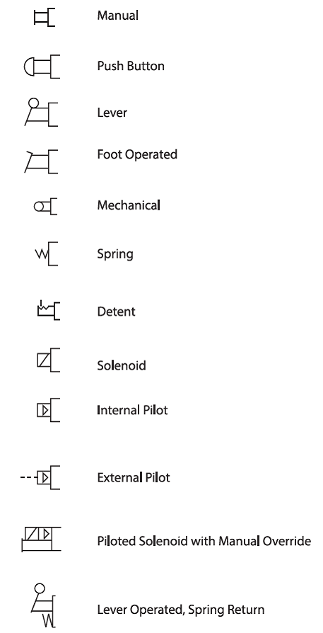
A basic pneumatic symbols PDF typically provides a comprehensive library of graphical representations for various components, including compressors, valves, actuators, and filters. For instance, a simple circle might represent a reservoir, while a rectangle with an arrow indicates a single-acting cylinder.
Understanding these symbols offers several significant benefits. Firstly, it facilitates effective communication among engineers, technicians, and operators, ensuring everyone is on the same page. Secondly, accurate interpretation of pneumatic diagrams enables efficient troubleshooting and maintenance, minimizing downtime. Finally, a strong grasp of these symbols empowers engineers to design robust and reliable pneumatic systems.
Developing a working knowledge of pneumatic symbols involves consistent practice and access to reliable resources like a basic pneumatic symbols PDF. Regularly reviewing these diagrams and applying the knowledge in practical scenarios can significantly enhance one's understanding.
A practical checklist for interpreting pneumatic schematics might include: Identify the main components, trace the flow of compressed air, understand the function of each valve, and analyze the overall system operation.
Resources for further learning include online tutorials, textbooks on fluid power systems, and specialized software for designing pneumatic circuits. Many websites offer downloadable basic pneumatic symbols PDF documents, providing a convenient reference.
Advantages and Disadvantages of using Standardized Pneumatic Symbols
| Advantages | Disadvantages |
|---|---|
| Clear communication | Requires initial learning |
| Efficient troubleshooting | Potential for misinterpretation if standards are not followed |
| Standardized design | Keeping up with standard revisions |
Best Practices: 1. Use the latest ISO standard. 2. Ensure clarity and readability in diagrams. 3. Label all components clearly. 4. Use consistent line weights and symbol sizes. 5. Document any deviations from standard symbols.
Real-world examples: 1. Automated assembly lines. 2. Packaging machinery. 3. Robotics. 4. Material handling systems. 5. Process control systems.
Challenges and Solutions: 1. Difficulty finding updated symbols (Solution: refer to ISO website). 2. Complex diagrams (Solution: break down into smaller circuits). 3. Misinterpretation of symbols (Solution: provide training and clear documentation). 4. Inconsistent use of symbols (Solution: enforce standardization within the organization). 5. Lack of access to reference materials (Solution: provide readily accessible pneumatic symbols PDF).
FAQ: 1. What is the symbol for a pressure relief valve? 2. How do I represent a flow control valve? 3. What does a double-acting cylinder symbol look like? 4. Where can I find a comprehensive pneumatic symbols PDF? 5. How often are pneumatic symbols updated? 6. What is the importance of ISO standards in pneumatic symbols? 7. Are there different symbol sets for different industries? 8. How can I learn more about interpreting pneumatic diagrams?
Tips and Tricks: Familiarize yourself with common symbol groupings. Practice tracing airflow through diagrams. Utilize online resources for interactive learning. Create your own symbol library for quick reference.
In conclusion, the seemingly simple lines and shapes of pneumatic symbols hold a remarkable power. They are the key to understanding, designing, and maintaining the intricate systems that power countless industrial processes. Embracing the elegance of these schematic representations, armed with resources like a readily available basic pneumatic symbols PDF, empowers us to navigate the world of pneumatics with confidence and precision. By adhering to best practices and continuously expanding our knowledge of this visual language, we can unlock the full potential of pneumatic technology. Take the time to delve deeper into this fascinating world, explore the available resources, and discover the profound impact of understanding pneumatic symbols on the efficiency and effectiveness of your work with pneumatic systems. It’s an investment that will undoubtedly pay dividends in the long run.
Fleur de sel the delicate salt thats transforming cuisine
The power of pull me up lyrics exploring meaning and impact
Unveiling history old english last names in the 1800s


