Decoding Electrical Schematics: A Guide to Circuit Symbols
Imagine trying to assemble a complex puzzle without knowing what the individual pieces represent. That's akin to working with electrical circuits without understanding schematic symbols. These symbols, a visual language for electronics, are essential for anyone working with circuits, from seasoned engineers to hobbyists. They provide a concise and standardized way to represent electrical components and their interconnections within a circuit.
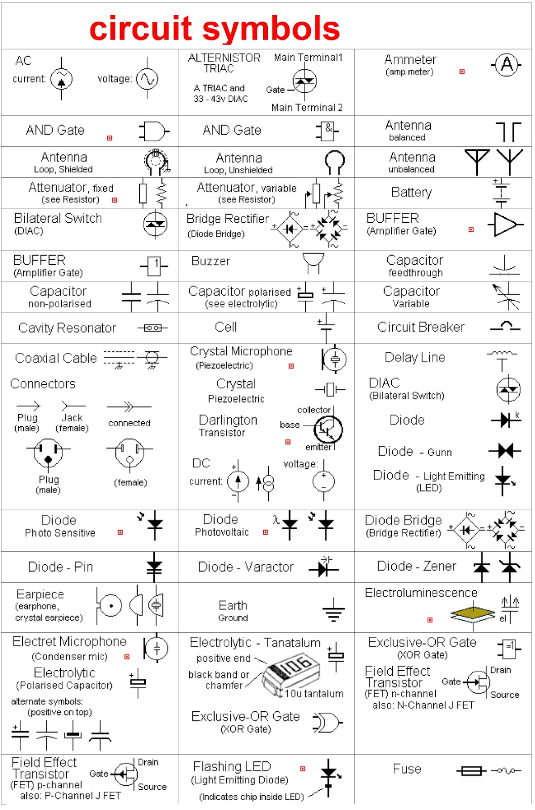
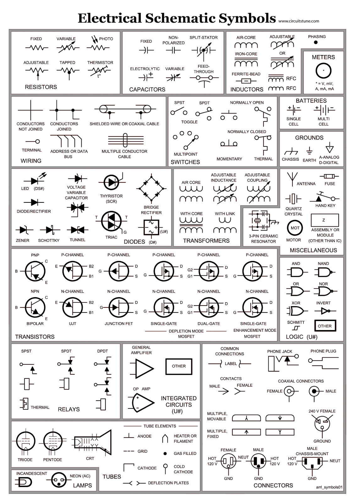
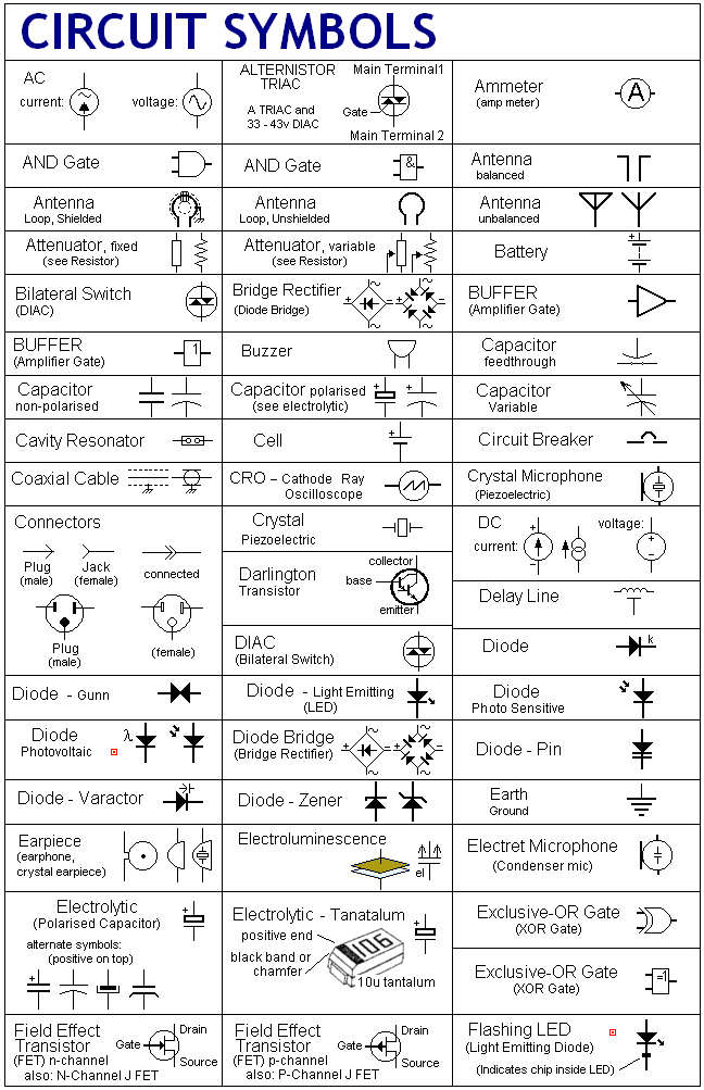
Electrical schematic symbols represent the various elements within an electrical system, such as resistors, capacitors, switches, and power sources. This standardized representation allows engineers and technicians to easily communicate and understand circuit designs, regardless of their background or language. These symbols are the building blocks of circuit diagrams, providing a roadmap for how electricity flows and how components interact.
The origins of electrical schematic symbols can be traced back to the early days of electrical experimentation, evolving alongside the technology itself. As circuits became more complex, the need for a standardized visual representation became apparent. Over time, symbols were developed and refined, leading to the internationally recognized standards we use today. These symbols are crucial for documenting circuits, troubleshooting issues, and sharing designs across different teams and industries.
One of the main issues related to electrical schematic diagrams is the potential for misinterpretation. A misplaced symbol or an incorrect connection can lead to malfunctioning circuits or even dangerous situations. Therefore, accurate and consistent use of these symbols is paramount. Understanding the nuances of each symbol, including its orientation and specific variations, is crucial for avoiding errors and ensuring the correct functionality of the designed circuit.
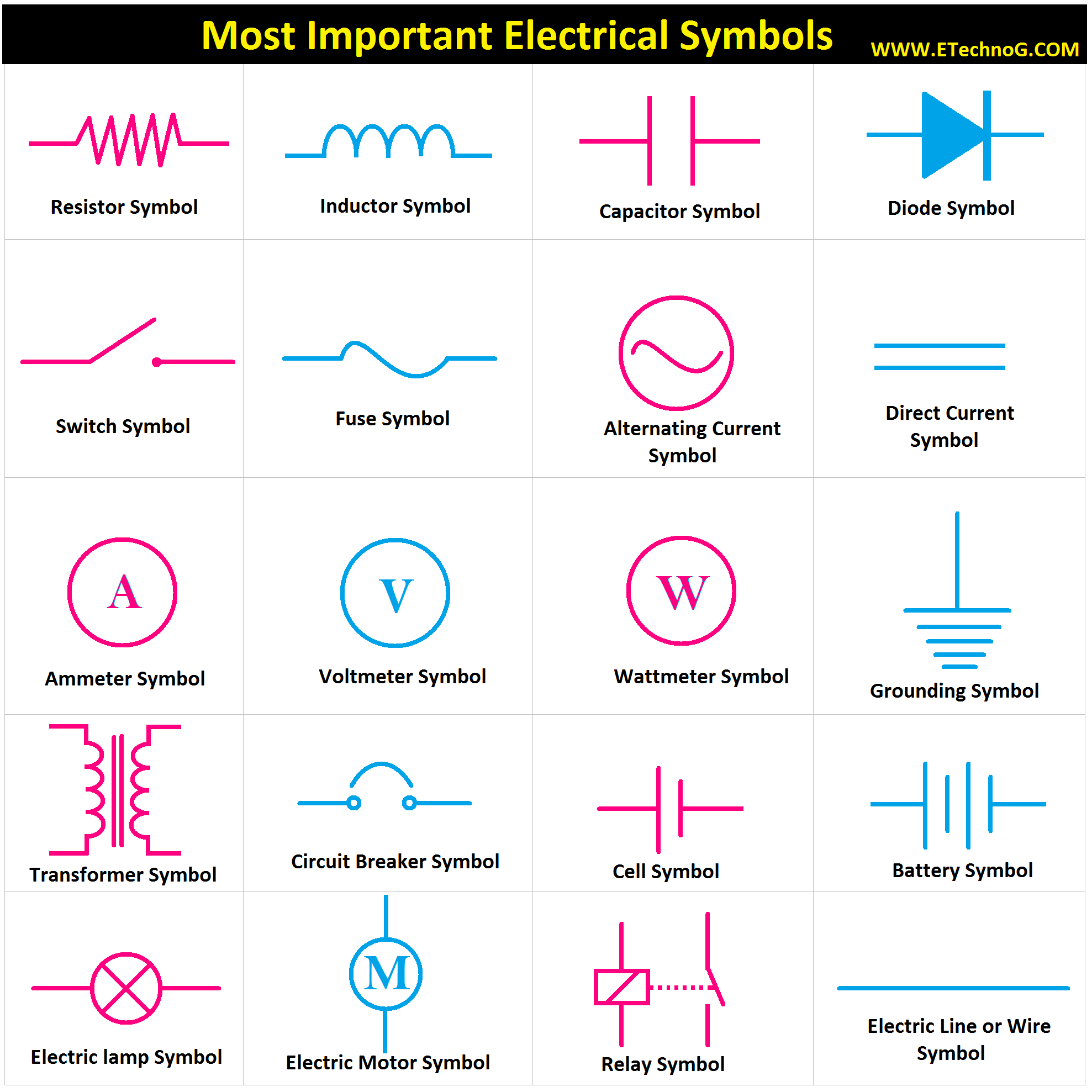
A resistor, for example, is represented by a zig-zag line, symbolizing its function of impeding current flow. A capacitor, on the other hand, is symbolized by two parallel lines, reflecting its ability to store electrical charge. Each symbol has a specific meaning and function, allowing complex circuits to be represented in a clear and concise manner. Understanding the library of these symbols opens the door to interpreting and designing electrical systems.
One key benefit of using a standard set of electrical schematic symbols is the universal understanding it facilitates. Engineers and technicians worldwide can interpret a circuit diagram regardless of language barriers, enabling efficient collaboration and knowledge sharing. This standardized communication ensures consistency and reduces the risk of misinterpretations during design, construction, and maintenance of electrical systems.
Another advantage is the streamlined troubleshooting process provided by using schematic diagrams. By visually tracing the connections and components represented by symbols, technicians can easily identify potential faults or areas requiring attention. This visual representation simplifies the process of diagnosing problems and significantly speeds up repairs, minimizing downtime and optimizing system performance.
Finally, schematic diagrams using standardized symbols are essential for documentation and communication of circuit designs. They serve as a blueprint for future modifications, upgrades, and maintenance. These diagrams make it easier to understand the circuit's functionality, enabling engineers to build upon existing designs or adapt them to new applications, fostering innovation and continuous improvement.
Understanding and utilizing electrical schematic symbols effectively involves a few key practices. Start by familiarizing yourself with the common symbols representing fundamental components like resistors, capacitors, and inductors. Then, practice reading and interpreting simple circuit diagrams. Gradually move towards more complex circuits as your confidence grows. Online resources, textbooks, and software tools can greatly assist in this learning process.
Consider these best practices: 1. Maintain consistency in symbol usage throughout your diagrams. 2. Clearly label all components and connections. 3. Organize the diagram logically to enhance readability. 4. Use a consistent scale for component sizes. 5. Regularly review and update your diagrams as the circuit evolves.
Advantages and Disadvantages of Standardized Schematic Symbols
| Advantages | Disadvantages |
|---|---|
| Universal understanding | Requires initial learning curve |
| Streamlined troubleshooting | Potential for misinterpretation if not used correctly |
| Effective documentation | Can become complex for very large circuits |
Real-world examples of schematic diagrams can be found in numerous electronic devices. From the simple circuitry of a flashlight to the complex network within a smartphone, these diagrams provide the roadmap for how these devices function. They are essential tools for designing, manufacturing, and repairing electronic systems across various industries.
One common challenge in working with schematics is keeping up with the evolving standards and new symbols. Continuous learning and staying updated with the latest industry practices is essential for maintaining accuracy and understanding. Another challenge can be interpreting complex diagrams with numerous interconnected components. Breaking down the circuit into smaller, manageable sections can simplify the analysis process.
Frequently asked questions include: What is the symbol for a diode? What does a ground symbol represent? How is a transistor depicted in a schematic? What is the difference between a normally open and normally closed switch? How do I represent a power source? What is the symbol for a fuse? How do I represent a connection point? What are the standard symbols for logic gates? These questions highlight the importance of understanding individual component representation within a circuit.
One helpful tip is to use software tools specifically designed for creating and simulating circuit diagrams. These tools often have built-in libraries of standard symbols and can automate many aspects of the design process. They also allow for simulation and testing of the circuit before physical implementation, saving time and resources.
In conclusion, electrical schematic symbols are the fundamental language of circuit design. Their standardized representation enables clear communication, efficient troubleshooting, and detailed documentation of electrical systems. From simple circuits to complex electronic devices, these symbols are essential for anyone working with electronics. Mastering the art of interpreting and using these symbols empowers individuals to design, analyze, and troubleshoot circuits effectively. Continuous learning and adherence to best practices are key to staying proficient in this constantly evolving field. Embrace the visual language of circuits, and unlock the world of electronics. By understanding and applying these principles, you can confidently navigate the intricate world of electrical schematics and harness the power of circuit design.
Unlocking the secrets of the zener diode symbol
Unleash your inner baker party cupcake decorating kits
Unlocking science mastery form 1 science exercises with answers

.jpg)


